Plant Components

Inside Upper Puwa-I

The main parts of the plant, from the two intakes to the switchyard.

Component by Component

How the Plant Is Built

Photos and key dimensions for each part of the scheme.

Headworks
01 / 07

Headworks

Two intakes feed the plant. On the Thulo Puwa Khola, a side intake with a gravel trap (8 m × 2.7 m) and a 27.5 m desander handles 1.50 m³/s. On the Sano Puwa Khola, a 9 m Tyrolean weir with its own gravel trap and a 24 m desander handles 1.10 m³/s.
Water Conveyance
02 / 07

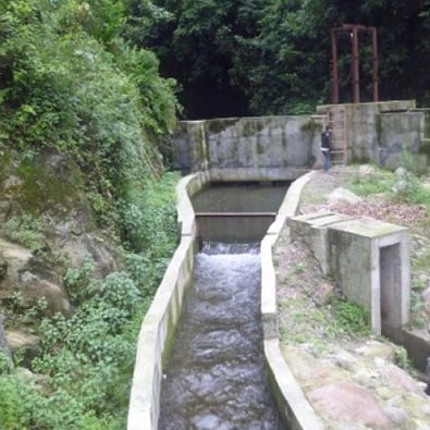
Water Conveyance

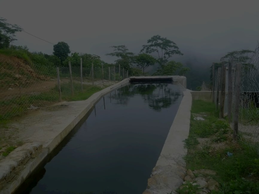
Two buried concrete canals, 2,133 m and 1,612 m long, run under the access road to a shared forebay (15 m × 5.5 m × 3.34 m) with spillway and flushing gates. From there a 460 m steel penstock, 1.1 m in diameter, drops to the powerhouse on 82 saddle supports and 10 anchor blocks.

Powerhouse
03 / 07

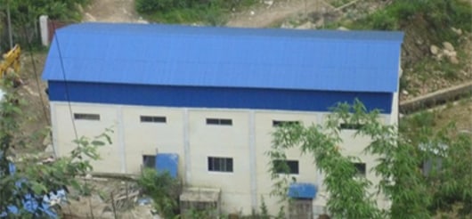
Powerhouse

A surface building of 336 m², 9.6 m high, housing the turbines and generators, the control room, the machine hall and drainage systems.

Generating Units
04 / 07

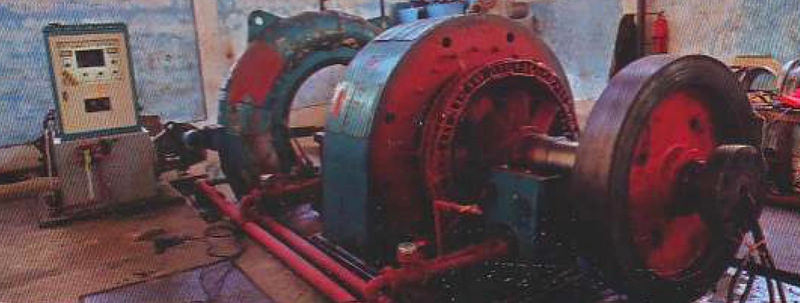
Generating Units

Two horizontal-axis Francis turbines rated at 1,000 rpm drive two 1,875 kVA synchronous generators at 6.6 kV and 50 Hz.

Control Room
05 / 07

Control Room

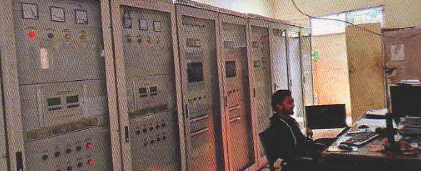
Operators run and monitor the units, the gates and the grid connection from the control room inside the powerhouse.

Tailrace
06 / 07

Tailrace

A 2 m wide, 1 m high box culvert on a 1:100 slope returns the water to the Thulo Puwa Khola. Tail water level is 1,231.5 m, and the 100-year flood level 1,232 m.

Switchyard
07 / 07

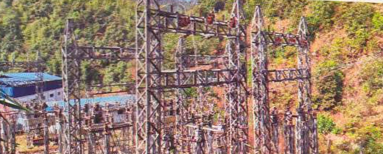
Switchyard

Switchgear and transformers connect the generating units to the national grid.

Powering Nepal's Progress, Sustainably

Get in Touch With Us

We're here to answer any questions you may have about the Upper Puwa-I Small Hydropower Project.