
The proposed waterway structures for conveying water are:
- Closed conduit type of canals
- Common forebay
- Penstock pipe
- Tailrace
Waterways such as the canal, forebay and tailrace were designed and constructed as non-pressure type or free flow structures. The penstock pipes were designed and constructed for a discharge of 2.365 m3/s. The hydraulic design of waterway structures was based on Manning’s formula. The coefficient of roughness adopted was 0.016 for concrete surface and 0.012 for steel. Sections of waterway structures were adopted as per the topographical condition of the site and hydraulic requirements.
Canals
The Thulo Puwa Khola canal was designed and constructed for a discharge of 1.36 m3/s. The 2133 m long rectangular and closed conduit type reinforced channel is 1.40 m wide and 0.95 m high including a fee board of 0.3 m. The canal has the bed slope of 1:500. Similarly, the Sano Puwa Khola was designed and constructed for a discharge of 1.005m3/s. The 1612 m long rectangular and conduit type reinforced channel is 1.20 m wide and 0.90 m high including a free board of 0.3 m. The canal bed slope is 1:500. Both the canals are buried below the proposed access road to the intakes of the Thulo Puwa and Sano Puwa.
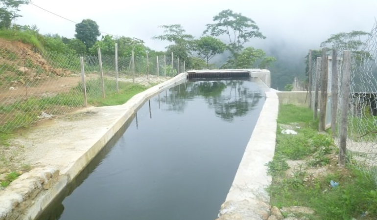
Common Forebay
A common forebay was designed and constructed for a discharge of 2.365 m3/s and was contributed by the canals of the Thulo Puwa Khola and the Sano Puwa Khola. The forebay normal operating level is 1402.71 m and the low water level is at an elevation of 1402.06 m. Moreover, the forebay is 15.0 m long, 5.5 m wide and 3.34 m deep including a free board of 0.3 m. Its transition length is 13.6 m. The forebay has a 12 m long spillway including two flushing gates of 0.5 m x 0.5 m size and 0.3 x 0.3 size.
Penstock Pipe
Water from the forebay has been conveyed through 1.1 m diameter and 460 m long penstock pipe. The pipe thickness varies between 8 mm and 16 mm. The penstock starting point is at an elevation of 1400.32 m and the penstock bifurcation level is at an elevation of 1235.78 m. Total number of anchor blocks and saddle supports provided were 10 and 82 respectively. Eight anchor blocks were provided for vertical bends and anchor block no 8 was provided for horizontal as well as vertical bend. Saddle supports were provided on 4.5m spacing between anchor blocks.
Powerhouse
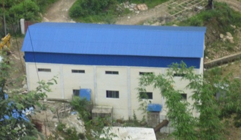
A surface powerhouse has been constructed on the left bank of the Thulo Puwa Khola. The powerhouse lies 25 m upstream of the confluence of two Puwa Khola. It is a reinforced cement concrete structure that houses two horizontal axis generating units. The main machine floor consists of two Francis Turbines, two generators, inlet valves, a maintenance and erection bay. An overhead traveling crane is installed to facilitate the installation and maintenance of powerhouse machines. The powerhouse roofing is of corrugated galvanize iron sheets resting on a steel truss structure seated on reinforced cement concrete column. The floor area of the powerhouse is 336 m2 and its height from the lowest foundation level to the roof ridge is 9.60 m.A row of windows has been provided in the powerhouse for lighting and ventilation. Moreover, a medium sized access door and a large shutter door is provided to transport machine laden trucks. Power station area have been fenced for protection from intruders. The plan and section of the powerhouse are shown in Annex A- As Built Drawing .
Machine Area
This area has accommodate turbines, generators, inlet valves, governors, powerhouse auxiliary system such as generator cooling system, turbine cooling system including lubricating system. In addition, fire fighting arrangements for the powerhouse are also located in this area. An overhead traveling crane is provided in the maintenance bay. A large shutter opening door is provided to ease transportation loading and unloading of heavy machines.
Control Room
The control room with display panels is provided which will help operate the power plant smoothly.
Other Facilities
A water treatment plant is provided outside the powerhouse for which water will be tapped from the tailrace. A stone masonry peripheral drainage has been constructed around the powerhouse to drain rain water to the Thulo Puwa Khola. Standby drainage pumps are provided at safe elevation to pump and drained water to the tailrace in case of emergency. A septic tank with a soak pit is provided near the powerhouse area to manage night soil.